
What Best suitable Arduino board for my project?
There are many Arduino microcontrollers in the market, but we need to evaluate what best suites your robot project.
Arduino Leonardo
 |
| Arduino Leonardo Board |
The Arduino Leonardo is a micro controller board based on the ATmega32u4 (data sheet). It has 20 digital input/output pins (of which 7 can be used as PWN outputs and 12 as analog inputs), a 16 MHz crystal oscillator, a micro USB connection, a power jack, an ICSP header, and a reset button. It contains everything needed to support the micro controller; simply connect it to a computer with a USB cable or power it with a AC-to-DC adapter or battery to get started.
The Leonardo differs from all preceding boards in that the ATmega32u4 has built-in USB communication, eliminating the need for a secondary processor. This allows the Leonardo to appear to a connected computer as a mouse and keyboard, in addition to a virtual (CDC) serial / COM port. It also has other implications for the behavior of the board.
The ATmega32u4 has 32 KB (with 4 KB used for the boot loader). It also has 2.5 KB of SRAM and 1 KB of EEPROM (which can be read and written with the EEPROM
Since the board does not have a dedicated chip to handle serial communication, the serial port is virtual. When you plug in Leonardo to the PC, it creates a serial instance of the USB’s Connected Device Class (CDC) driver. Every time you reset the board, the USB serial connection is broken and re-established. The board disappears from the list of serial ports in your PC, and the list re-enumerates. This difference has implications for driver installation, uploading and communication. Details can be found here.
The Arduino Mega 2560 is a microcontroller board based on the ATmega2560 (datasheet). It has 54 digital input/output pins (of which 14 can be used as PWM outputs), 16 analog inputs, 4 UARTs (hardware serial ports), a 16 MHz crystal oscillator, a USB connection, a power jack, an ICSP header, and a reset button. It contains everything needed to support the microcontroller; simply connect it to a computer with a USB cable or power it with a AC-to-DC adapter or battery to get started. The Mega is compatible with most shields designed for the Arduino Duemilanove or Diecimila.
The Mega 2560 is an update to the Arduino Mega, which it replaces.
The Arduino Mega can be powered via the USB connection or with an external power supply. The power source is selected automatically.
External (non-USB) power can come either from an AC-to-DC adapter (wall-wart) or battery. The adapter can be connected by plugging a 2.1mm center-positive plug into the board's power jack. Leads from a battery can be inserted in the Gnd and Vin pin headers of the POWER connector.
The board can operate on an external supply of 6 to 20 volts. If supplied with less than 7V, however, the 5V pin may supply less than five volts and the board may be unstable. If using more than 12V, the voltage regulator may overheat and damage the board. The recommended range is 7 to 12 volts.
The Mega2560 differs from all preceding boards in that it does not use the FTDI USB-to-serial driver chip. Instead, it features the ATmega16U2 (ATmega8U2 in the revision 1 and revision 2 boards) programmed as a USB-to-serial converter.
Revision 2 of the Mega2560 board has a resistor pulling the 8U2 HWB line to ground, making it easier to put into DFU mode.
Revision 3 of the board has the following new features:
The ATmega2560 has 256 KB of flash memory for storing code (of which 8 KB is used for the bootloader), 8 KB of SRAM and 4 KB of EEPROM (which can be read and written with the EEPROM library).
Each of the 54 digital pins on the Mega can be used as an input or output, using pinMode(), digitalWrite(), and digitalRead() functions. They operate at 5 volts. Each pin can provide or receive a maximum of 40 mA and has an internal pull-up resistor (disconnected by default) of 20-50 kOhms. In addition, some pins have specialized functions:
There are a couple of other pins on the board:
The Arduino Mega2560 has a number of facilities for communicating with a computer, another Arduino, or other microcontrollers. The ATmega2560 provides four hardware UARTs for TTL (5V) serial communication. An ATmega16U2 (ATmega 8U2 on the revision 1 and revision 2 boards) on the board channels one of these over USB and provides a virtual com port to software on the computer (Windows machines will need a .inf file, but OSX and Linux machines will recognize the board as a COM port automatically. The Arduino software includes a serial monitor which allows simple textual data to be sent to and from the board. The RX and TX LEDs on the board will flash when data is being transmitted via the ATmega8U2/ATmega16U2 chip and USB connection to the computer (but not for serial communication on pins 0 and 1).
A Software Serial library allows for serial communication on any of the Mega2560's digital pins.
The ATmega2560 also supports TWI and SPI communication. The Arduino software includes a Wire library to simplify use of the TWI bus; see the documentation for details. For SPI communication, use the SPI library.
The Arduino Mega can be programmed with the Arduino software .The ATmega2560 on the Arduino Mega comes preburned with a bootloader that allows you to upload new code to it without the use of an external hardware programmer. It communicates using the original STK500 protocol (reference, C header files).
You can also bypass the bootloader and program the microcontroller through the ICSP (In-Circuit Serial Programming) header; see these instructions for details. The ATmega16U2 (or 8U2 in the rev1 and rev2 boards) firmware source code is available in the Arduino repository. The ATmega16U2/8U2 is loaded with a DFU bootloader, which can be activated by:
The Arduino Uno is an open-source microcontroller board based on the Microchip ATmega328P microcontroller and developed by Arduino.cc The board is equipped with sets of digital and analog input/output (I/O) pins that may be interfaced to various expansion boards (shields) and other circuits. The board has 14 digital I/O pins (six capable of PWM output), 6 analog I/O pins, and is programmable with the Arduino IDE (Integrated Development Environment), via a type B USB cable. It can be powered by the USB cable or by an external 9-volt battery, though it accepts voltages between 7 and 20 volts. It is also similar to the Arduino Nano and Leonardo.The hardware reference design is distributed under a Creative Commons Attribution Share-Alike 2.5 license and is available on the Arduino website. Layout and production files for some versions of the hardware are also available.
Features of Arduino Leonardo
- Input voltage: 7V-12V
- Operating voltage: 2.7V-5.5V
- 12 analogue input pins and seven pulse-width-modulated (PWM) outputs
- 32kB flash memory
- 1kB EEPROM
- 2.5kB SRAM
- 40mA per I/O pin current (DC)
Since the board does not have a dedicated chip to handle serial communication, the serial port is virtual. When you plug in Leonardo to the PC, it creates a serial instance of the USB’s Connected Device Class (CDC) driver. Every time you reset the board, the USB serial connection is broken and re-established. The board disappears from the list of serial ports in your PC, and the list re-enumerates. This difference has implications for driver installation, uploading and communication. Details can be found here.
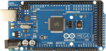
Arduino mega

 |
| Front and back view of Arduino Mega board |
The Mega 2560 is an update to the Arduino Mega, which it replaces.
Features of Arduino Mega
- Microcontroller ATmega2560
- Operating Voltage 5V
- Input Voltage (recommended) 7-12V
- Input Voltage (limits) 6-20V
- Digital I/O Pins 54 (of which 14 provide PWM output)
- Analog Input Pins 16
- DC Current per I/O Pin 40 mA
- DC Current for 3.3V Pin 50 mA
- Flash Memory 256 KB of which 8 KB used by bootloader
- SRAM 8 KB
- EEPROM 4 KB
- Clock Speed 16 MHz
Power source for Arduino Mega
External (non-USB) power can come either from an AC-to-DC adapter (wall-wart) or battery. The adapter can be connected by plugging a 2.1mm center-positive plug into the board's power jack. Leads from a battery can be inserted in the Gnd and Vin pin headers of the POWER connector.
The board can operate on an external supply of 6 to 20 volts. If supplied with less than 7V, however, the 5V pin may supply less than five volts and the board may be unstable. If using more than 12V, the voltage regulator may overheat and damage the board. The recommended range is 7 to 12 volts.
The Mega2560 differs from all preceding boards in that it does not use the FTDI USB-to-serial driver chip. Instead, it features the ATmega16U2 (ATmega8U2 in the revision 1 and revision 2 boards) programmed as a USB-to-serial converter.
Revision 2 of the Mega2560 board has a resistor pulling the 8U2 HWB line to ground, making it easier to put into DFU mode.
Revision 3 of the board has the following new features:
- 1.0 pinout: added SDA and SCL pins that are near to the AREF pin and two other new pins placed near to the RESET pin, the IOREF that allow the shields to adapt to the voltage provided from the board. In future, shields will be compatible both with the board that use the AVR, which operate with 5V and with the Arduino Due that operate with 3.3V. The second one is a not connected pin, that is reserved for future purposes.
- Stronger RESET circuit.
- Atmega 16U2 replace the 8U2.
- Vin. The input voltage to the Arduino board when it's using an external power source (as opposed to 5 volts from the USB connection or other regulated power source). You can supply voltage through this pin, or, if supplying voltage via the power jack, access it through this pin.
- 5V. The regulated power supply used to power the microcontroller and other components on the board. This can come either from VIN via an on-board regulator, or be supplied by USB or another regulated 5V supply.
- 3V3. A 3.3 volt supply generated by the on-board regulator. Maximum current draw is 50 mA.
- GND. Ground pins.
Memory of Arduino Mega
Inputs and Outputs of an Arduino Mega
- Serial: 0 (RX) and 1 (TX); Serial 1: 19 (RX) and 18 (TX); Serial 2: 17 (RX) and 16 (TX); Serial 3: 15 (RX) and 14 (TX). Used to receive (RX) and transmit (TX) TTL serial data. Pins 0 and 1 are also connected to the corresponding pins of the ATmega16U2 USB-to-TTL Serial chip.
- External Interrupts: 2 (interrupt 0), 3 (interrupt 1), 18 (interrupt 5), 19 (interrupt 4), 20 (interrupt 3), and 21 (interrupt 2). These pins can be configured to trigger an interrupt on a low value, a rising or falling edge, or a change in value. See the attachInterrupt() function for details.
- PWM: 0 to 13. Provide 8-bit PWM output with the analogWrite() function.
- SPI: 50 (MISO), 51 (MOSI), 52 (SCK), 53 (SS). These pins support SPI communication using the SPI library. The SPI pins are also broken out on the ICSP header, which is physically compatible with the Uno, Duemilanove and Diecimila.
- LED: 13. There is a built-in LED connected to digital pin 13. When the pin is HIGH value, the LED is on, when the pin is LOW, it's off.
- TWI: 20 (SDA) and 21 (SCL). Support TWI communication using the Wire library. Note that these pins are not in the same location as the TWI pins on the Duemilanove or Diecimila.
There are a couple of other pins on the board:
- AREF. Reference voltage for the analog inputs. Used with analogReference().
- Reset. Bring this line LOW to reset the microcontroller. Typically used to add a reset button to shields which block
Communication of Arduino Mega
A Software Serial library allows for serial communication on any of the Mega2560's digital pins.
The ATmega2560 also supports TWI and SPI communication. The Arduino software includes a Wire library to simplify use of the TWI bus; see the documentation for details. For SPI communication, use the SPI library.
Programming for Arduino Mega
You can also bypass the bootloader and program the microcontroller through the ICSP (In-Circuit Serial Programming) header; see these instructions for details. The ATmega16U2 (or 8U2 in the rev1 and rev2 boards) firmware source code is available in the Arduino repository. The ATmega16U2/8U2 is loaded with a DFU bootloader, which can be activated by:
- On Rev1 boards: connecting the solder jumper on the back of the board (near the map of Italy) and then resetting the 8U2.
- On Rev2 or later boards: there is a resistor that pulling the 8U2/16U2 HWB line to ground, making it easier to put into DFU mode. You can then use Atmel's FLIP software (Windows) or the DFU programmer (Mac OS X and Linux) to load a new firmware. Or you can use the ISP header with an external programmer (overwriting the DFU bootloader). See this user-contributed tutorial for more information.
Automatic (Software) Reset of Arduino Mega
Rather then requiring a physical press of the reset button before an upload, the Arduino Mega2560 is designed in a way that allows it to be reset by software running on a connected computer. One of the hardware flow control lines (DTR) of the ATmega8U2 is connected to the reset line of the ATmega2560 via a 100 nanofarad capacitor. When this line is asserted (taken low), the reset line drops long enough to reset the chip. The Arduino software uses this capability to allow you to upload code by simply pressing the upload button in the Arduino environment. This means that the bootloader can have a shorter timeout, as the lowering of DTR can be well-coordinated with the start of the uploadArduino Uno
 |
| Arduino Uno Board |
The Arduino Uno is an open-source microcontroller board based on the Microchip ATmega328P microcontroller and developed by Arduino.cc The board is equipped with sets of digital and analog input/output (I/O) pins that may be interfaced to various expansion boards (shields) and other circuits. The board has 14 digital I/O pins (six capable of PWM output), 6 analog I/O pins, and is programmable with the Arduino IDE (Integrated Development Environment), via a type B USB cable. It can be powered by the USB cable or by an external 9-volt battery, though it accepts voltages between 7 and 20 volts. It is also similar to the Arduino Nano and Leonardo.The hardware reference design is distributed under a Creative Commons Attribution Share-Alike 2.5 license and is available on the Arduino website. Layout and production files for some versions of the hardware are also available.
The word "uno" means "one" in Italian and was chosen to mark the initial release of Arduino Software.The Uno board is the first in a series of USB-based Arduino boards;it and version 1.0 of the Arduino IDE were the reference versions of Arduino, which have now evolved to newer releases The ATmega328 on the board comes preprogrammed with a bootloader that allows uploading new code to it without the use of an external hardware programmer.
While the Uno communicates using the original STK500 protocol,it differs from all preceding boards in that it does not use the FTDI USB-to-serial driver chip. Instead, it uses the Atmega16U2 (Atmega8U2 up to version R2) programmed as a USB-to-serial converter.
Technical specifications of Arduino Uno
 |
| Pin information of Arduino Uno Board |
- Operating Voltage: 5 Volts
- Input Voltage: 7 to 20 Volts
- Digital I/O Pins: 14 (of which 6 can provide PWM output)
- Analog Input Pins: 6
- DC Current per I/O Pin: 20 mA
- DC Current for 3.3V Pin: 50 mA
- Flash Memory: 32 KB of which 0.5 KB used by bootloader
- SRAM: 2 KB
- EEPROM: 1 KB
- Clock Speed: 16 MHz
- Length: 68.6 mm
- Width: 53.4 mm
- Weight: 25 g

General pin functioning of Arduino Uno
- LED: There is a built-in LED driven by digital pin 13. When the pin is high value, the LED is on, when the pin is low, it is off.
- VIN: The input voltage to the Arduino/Genuino board when it is using an external power source (as opposed to 5 volts from the USB connection or other regulated power source). You can supply voltage through this pin, or, if supplying voltage via the power jack, access it through this pin.
- 5V: This pin outputs a regulated 5V from the regulator on the board. The board can be supplied with power either from the DC power jack (7 - 20V), the USB connector (5V), or the VIN pin of the board (7-20V). Supplying voltage via the 5V or 3.3V pins bypasses the regulator, and can damage the board.
- 3V3: A 3.3 volt supply generated by the on-board regulator. Maximum current draw is 50 mA.
- GND: Ground pins.
- IOREF: This pin on the Arduino/Genuino board provides the voltage reference with which the microcontroller operates. A properly configured shield can read the IOREF pin voltage and select the appropriate power source, or enable voltage translators on the outputs to work with the 5V or 3.3V.
- Reset: Typically used to add a reset button to shields that block the one on the board.
Special pin Function of an Arduino Uno
Each of the 14 digital pins and 6 analog pins on the Uno can be used as an input or output, under software control (using pinMode(), digitalWrite(), and digitalRead() functions). They operate at 5 volts. Each pin can provide or receive 20 mA as the recommended operating condition and has an internal pull-up resistor (disconnected by default) of 20-50K ohm. A maximum of 40mA must not be exceeded on any I/O pin to avoid permanent damage to the microcontroller. The Uno has 6 analog inputs, labeled A0 through A5; each provides 10 bits of resolution (i.e. 1024 different values). By default, they measure from ground to 5 volts, though it is possible to change the upper end of the range using the AREF pin and the analogReference() function.
In addition, some pins have specialized functions:
- Serial / UART: pins 0 (RX) and 1 (TX). Used to receive (RX) and transmit (TX) TTL serial data. These pins are connected to the corresponding pins of the ATmega8U2 USB-to-TTL serial chip.
- External interrupts: pins 2 and 3. These pins can be configured to trigger an interrupt on a low value, a rising or falling edge, or a change in value.
- PWM (pulse-width modulation): pins 3, 5, 6, 9, 10, and 11. Can provide 8-bit PWM output with the analogWrite() function.
- SPI (Serial Peripheral Interface): pins 10 (SS), 11 (MOSI), 12 (MISO), and 13 (SCK). These pins support SPI communication using the SPI library.
- TWI (two-wire interface) / I²C: pin SDA (A4) and pin SCL (A5). Support TWI communication using the Wire library.
- AREF (analog reference): Reference voltage for the analog inputs.
Communication of Arduino Uno
The Arduino/Genuino Uno has a number of facilities for communicating with a computer, another Arduino/Genuino board, or other microcontrollers. The ATmega328 provides UART TTL (5V) serial communication, which is available on digital pins 0 (RX) and 1 (TX). An ATmega16U2 on the board channels this serial communication over USB and appears as a virtual com port to software on the computer. The 16U2 firmware uses the standard USB COM drivers, and no external driver is needed. However, on Windows, a .inf file is required. Arduino Software (IDE) includes a serial monitor which allows simple textual data to be sent to and from the board. The RX and TX LEDs on the board will flash when data is being transmitted via the USB-to-serial chip and USB connection to the computer (but not for serial communication on pins 0 and 1). A SoftwareSerial library allows serial communication on any of the Uno's digital pins.
Automatic reset of Arduino Uno
Rather than requiring a physical press of the reset button before an upload, the Arduino/Genuino Uno board is designed in a way that allows it to be reset by software running on a connected computer. One of the hardware flow control lines (DTR) of the ATmega8U2/16U2 is connected to the reset line of the ATmega328 via a 100 nanofarad capacitor. When this line is asserted (taken low), the reset line drops long enough to reset the chip.
This setup has other implications. When the Uno is connected to a computer running Mac OS X or Linux, it resets each time a connection is made to it from software (via USB). For the following half-second or so, the bootloader is running on the Uno. While it is programmed to ignore malformed data (i.e. anything besides an upload of new code), it will intercept the first few bytes of data sent to the board after a connection is opened.
No comments:
Post a Comment