Saturday, January 11, 2020

Classification of sensors


Types of Sensors


We live in a World of Sensors. You can find different types of Sensors in our homes, offices, cars etc. working to make our lives easier by turning on the lights by detecting our presence, adjusting the room temperature, detect smoke or fire, make us delicious coffee, open garage doors as soon as our car is near the door and many other tasks.
All these and many other automation tasks are possible because of Sensors. Before going in to the details of What is a Sensor, What are the Different Types of Sensors and Applications of these different types of Sensors, we will first take a look at a simple example of an automated system, which is possible because of Sensors (and many other components as well). 

Real Time Application of Sensors 

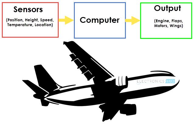
The example we are talking about here is the Autopilot System in aircrafts. Almost all civilian and military aircrafts have the feature of Automatic Flight Control system or sometimes called as Autopilot.
Types of Sensors Image 1
An Automatic Flight Control System consists of several sensors for various tasks like speed control, height, position, doors, obstacle, fuel, maneuvering and many more. A Computer takes data from all these sensors and processes them by comparing them with pre-designed values.
The computer then provides control signal to different parts like engines, flaps, rudders etc. that help in a smooth flight. The combination of Sensors, Computers and Mechanics makes it possible to run the plane in Autopilot Mode.
All the parameters i.e. the Sensors (which give inputs to the Computers), the Computers (the brains of the system) and the mechanics (the outputs of the system like engines and motors) are equally important in building a successful automated system.
But in this tutorial, we will be concentrating on the Sensors part of a system and look at different concepts associated with Sensors (like types, characteristics, classification etc.).

What is a Sensor?

There are numerous definitions as to what a sensor is but I would like to define a Sensor as an input device which provides an output (signal) with respect to a specific physical quantity (input).
The term “input device” in the definition of a Sensor means that it is part of a bigger system which provides input to a main control system (like a Processor or a Microcontroller).
Another unique definition of a Sensor is as follows: It is a device that converts signals from one energy domain to electrical domain. The definition of the Sensor can be understood if we take an example in to consideration.
Types of Sensors Image 2
The simplest example of a sensor is an LDR or a Light Dependent Resistor. It is a device, whose resistance varies according to intensity of light it is subjected to. When the light falling on an LDR is more, its resistance becomes very less and when the light is less, well, the resistance of the LDR becomes very high.
We can connect this LDR in a voltage divider (along with other resistor) and check the voltage drop across the LDR. This voltage can be calibrated to the amount of light falling on the LDR. Hence, a Light Sensor.
Now that we have seen what a sensor is, we will proceed further with the classification of Sensors.

Classification of Sensors

There are several classifications of sensors made by different authors and experts. Some are very simple and some are very complex. The following classification of sensors may already be used by an expert in the subject but this is a very simple classification of sensors.
In the first classification of the sensors, they are divided in to Active and Passive. Active Sensors are those which require an external excitation signal or a power signal.
Passive Sensors, on the other hand, do not require any external power signal and directly generates output response.
The other type of classification is based on the means of detection used in the sensor. Some of the means of detection are Electric, Biological, Chemical, Radioactive etc.
The next classification is based on conversion phenomenon i.e. the input and the output. Some of the common conversion phenomena are Photoelectric, Thermoelectric, Electrochemical, Electromagnetic, Thermo optic, etc.
The final classification of the sensors are Analog and Digital Sensors. Analog Sensors produce an analog output i.e. a continuous output signal with respect to the quantity being measured.
Digital Sensors, in contrast to Analog Sensors, work with discrete or digital data. The data in digital sensors, which is used for conversion and transmission, is digital in nature.  

Different Types of Sensors

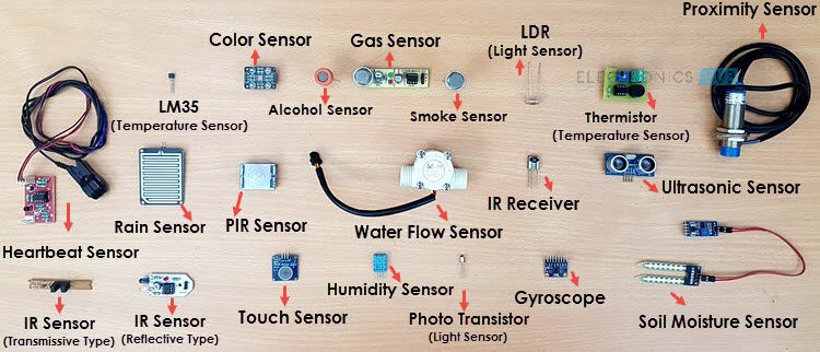
The following is a list of different types of sensors that are commonly used in various applications. All these sensors are used for measuring one of the physical properties like Temperature, Resistance, Capacitance, Conduction, Heat Transfer etc.
  • Temperature Sensor
  • Proximity Sensor
  • Accelerometer
  • IR Sensor (Infrared Sensor)
  • Pressure Sensor
  • Light Sensor
  • Ultrasonic Sensor
  • Smoke, Gas and Alcohol Sensor
  • Touch Sensor
  • Color Sensor
  • Humidity Sensor
  • Tilt Sensor
  • Flow and Level Sensor
We will see about few of the above mentioned sensors in brief. More information about the sensors will be added subsequently. A list of projects using the above sensors is given at the end of the page.

Temperature Sensor

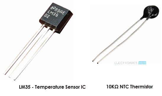
One of the most common and most popular sensor is the Temperature Sensor. A Temperature Sensor, as the name suggests, senses the temperature i.e. it measures the changes in the temperature.
Types of Sensors Image 3
In a Temperature Sensor, the changes in the Temperature correspond to change in its physical property like resistance or voltage.  
There are different types of Temperature Sensors like Temperature Sensor ICs (like LM35), Thermistors, Thermocouples, RTD (Resistive Temperature Devices), etc.
Temperature Sensors are used everywhere like computers, mobile phones, automobiles, air conditioning systems, industries etc.     
A simple project using LM35 (Celsius Scale Temperature Sensor) is implemented in this project: TEMPERATURE CONTROLLED SYSTEM.

Proximity Sensors

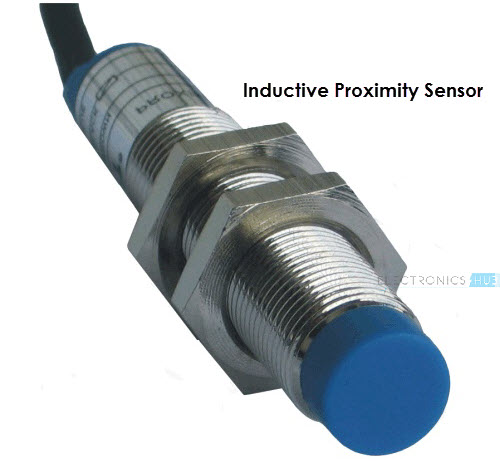
A Proximity Sensor is a non-contact type sensor that detects the presence of an object. Proximity Sensors can be implemented using different techniques like Optical (like Infrared or Laser), Ultrasonic, Hall Effect, Capacitive, etc.
Types of Sensors Image 4
Some of the applications of Proximity Sensors are Mobile Phones, Cars (Parking Sensors), industries (object alignment), Ground Proximity in Aircrafts, etc.
Proximity Sensor in Reverse Parking is implemented in this Project: REVERSE PARKING SENSOR CIRCUIT.  

Infrared Sensor (IR Sensor)

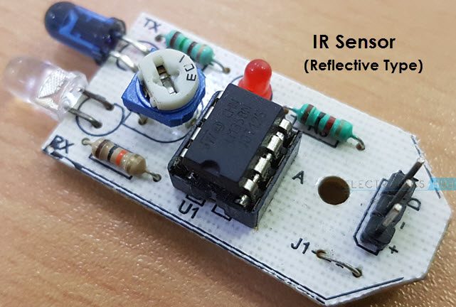
IR Sensors or Infrared Sensor are light based sensor that are used in various applications like Proximity and Object Detection. IR Sensors are used as proximity sensors in almost all mobile phones.
Types of Sensors Image 5
There are two types of Infrared or IR Sensors: Transmissive Type and Reflective Type. In Transmissive Type IR Sensor, the IR Transmitter (usually an IR LED) and the IR Detector (usually a Photo Diode) are positioned facing each other so that when an object passes between them, the sensor detects the object.
The other type of IR Sensor is a Reflective Type IR Sensor. In this, the transmitter and the detector are positioned adjacent to each other facing the object. When an object comes in front of the sensor, the sensor detects the object.
Different applications where IR Sensor is implemented are Mobile Phones, Robots, Industrial assembly, automobiles etc.
A small project, where IR Sensors are used to turn on street lights: STREET LIGHTS USING IR SENSORS.

Ultrasonic Sensor  

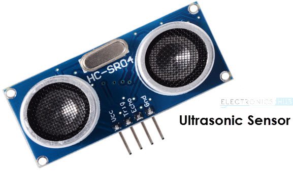
An Ultrasonic Sensor is a non-contact type device that can be used to measure distance as well as velocity of an object. An Ultrasonic Sensor works based on the properties of the sound waves with frequency greater than that of the human audible range.
Types of Sensors Image 6
Using the time of flight of the sound wave, an Ultrasonic Sensor can measure the distance of the object (similar to SONAR). The Doppler Shift property of the sound wave is used to measure the velocity of an object.
Arduino based Range Finder is a simple project using Ultrasonic Sensor: PORTABLE ULTRASONIC RANGE METER
The following is a small list of projects based on few of the above mentioned Sensors. 
Light Sensor – LIGHT DETECTOR USING LDR 
Smoke Sensor – SMOKE DETECTOR ALARM CIRCUIT
Color Sensor – ARDUINO BASED COLOR DETECTOR
Humidity Sensor – DHT11 HUMIDITY SENSOR ON ARDUINO
In this article, we have seen about What is a Sensor, what are the classification of sensors and different Types of Sensors along with their practical applications.  

What Best suitable Arduino board for my project?

What Best suitable Arduino board for my project?

There are many Arduino microcontrollers in the market, but we need to evaluate what best suites your robot project.

Arduino Leonardo


Image result for arduino leonardo
Arduino Leonardo Board 

 The Arduino Leonardo is a micro controller board based on the ATmega32u4 (data sheet). It has 20 digital input/output pins (of which 7 can be used as PWN outputs and 12 as analog inputs), a 16 MHz crystal oscillator, a micro USB connection, a power jack, an ICSP header, and a reset button. It contains everything needed to support the micro controller; simply connect it to a computer with a USB cable or power it with a AC-to-DC adapter or battery to get started.
The Leonardo differs from all preceding boards in that the ATmega32u4 has built-in USB communication, eliminating the need for a secondary processor. This allows the Leonardo to appear to a connected computer as a mouse and keyboard, in addition to a virtual (CDC) serial / COM port. It also has other implications for the behavior of the board.
The ATmega32u4 has 32 KB (with 4 KB used for the boot loader). It also has 2.5 KB of SRAM and 1 KB of EEPROM (which can be read and written with the EEPROM

Features of Arduino Leonardo 

  1.  Input voltage: 7V-12V
  2.  Operating voltage: 2.7V-5.5V
  3.  12 analogue input pins and seven pulse-width-modulated (PWM) outputs
  4.  32kB flash memory
  5.  1kB EEPROM
  6.  2.5kB SRAM
  7.  40mA per I/O pin current (DC)
The Leonardo board uses a single microcontroller to run your sketches as well as communicate with your PC using USB. This allows Leonardo far more flexibility in its communication with the computer. It also helps to lower the cost of the board.
Since the board does not have a dedicated chip to handle serial communication, the serial port is virtual. When you plug in Leonardo to the PC, it creates a serial instance of the USB’s Connected Device Class (CDC) driver. Every time you reset the board, the USB serial connection is broken and re-established. The board disappears from the list of serial ports in your PC, and the list re-enumerates. This difference has implications for driver installation, uploading and communication. Details can be found here.


Arduino mega 


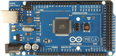
ArduinoMega2560 R3 Front.jpg
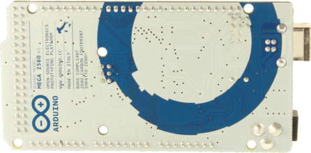
ArduinoMega2560 R3 Back.jpg
Front and back view of Arduino Mega board 

The Arduino Mega 2560 is a microcontroller board based on the ATmega2560 (datasheet). It has 54 digital input/output pins (of which 14 can be used as PWM outputs), 16 analog inputs, 4 UARTs (hardware serial ports), a 16 MHz crystal oscillator, a USB connection, a power jack, an ICSP header, and a reset button. It contains everything needed to support the microcontroller; simply connect it to a computer with a USB cable or power it with a AC-to-DC adapter or battery to get started. The Mega is compatible with most shields designed for the Arduino Duemilanove or Diecimila.
The Mega 2560 is an update to the Arduino Mega, which it replaces.

Features of Arduino Mega

  1. Microcontroller ATmega2560
  2. Operating Voltage 5V
  3. Input Voltage (recommended) 7-12V
  4. Input Voltage (limits) 6-20V
  5. Digital I/O Pins 54 (of which 14 provide PWM output)
  6. Analog Input Pins 16
  7. DC Current per I/O Pin 40 mA
  8. DC Current for 3.3V Pin 50 mA
  9. Flash Memory 256 KB of which 8 KB used by bootloader
  10. SRAM 8 KB
  11. EEPROM 4 KB
  12. Clock Speed 16 MHz

Power source for Arduino Mega


The Arduino Mega can be powered via the USB connection or with an external power supply. The power source is selected automatically.
External (non-USB) power can come either from an AC-to-DC adapter (wall-wart) or battery. The adapter can be connected by plugging a 2.1mm center-positive plug into the board's power jack. Leads from a battery can be inserted in the Gnd and Vin pin headers of the POWER connector.
The board can operate on an external supply of 6 to 20 volts. If supplied with less than 7V, however, the 5V pin may supply less than five volts and the board may be unstable. If using more than 12V, the voltage regulator may overheat and damage the board. The recommended range is 7 to 12 volts.
The Mega2560 differs from all preceding boards in that it does not use the FTDI USB-to-serial driver chip. Instead, it features the ATmega16U2 (ATmega8U2 in the revision 1 and revision 2 boards) programmed as a USB-to-serial converter.
Revision 2 of the Mega2560 board has a resistor pulling the 8U2 HWB line to ground, making it easier to put into DFU mode.
Revision 3 of the board has the following new features:
  • 1.0 pinout: added SDA and SCL pins that are near to the AREF pin and two other new pins placed near to the RESET pin, the IOREF that allow the shields to adapt to the voltage provided from the board. In future, shields will be compatible both with the board that use the AVR, which operate with 5V and with the Arduino Due that operate with 3.3V. The second one is a not connected pin, that is reserved for future purposes.
  • Stronger RESET circuit.
  • Atmega 16U2 replace the 8U2.
The power pins are as follows:
  • Vin. The input voltage to the Arduino board when it's using an external power source (as opposed to 5 volts from the USB connection or other regulated power source). You can supply voltage through this pin, or, if supplying voltage via the power jack, access it through this pin.
  • 5V. The regulated power supply used to power the microcontroller and other components on the board. This can come either from VIN via an on-board regulator, or be supplied by USB or another regulated 5V supply.
  • 3V3. A 3.3 volt supply generated by the on-board regulator. Maximum current draw is 50 mA.
  • GND. Ground pins.

Memory of Arduino Mega


The ATmega2560 has 256 KB of flash memory for storing code (of which 8 KB is used for the bootloader), 8 KB of SRAM and 4 KB of EEPROM (which can be read and written with the EEPROM library).

Inputs and Outputs of an Arduino Mega


Each of the 54 digital pins on the Mega can be used as an input or output, using pinMode(), digitalWrite(), and digitalRead() functions. They operate at 5 volts. Each pin can provide or receive a maximum of 40 mA and has an internal pull-up resistor (disconnected by default) of 20-50 kOhms. In addition, some pins have specialized functions:
  • Serial: 0 (RX) and 1 (TX); Serial 1: 19 (RX) and 18 (TX); Serial 2: 17 (RX) and 16 (TX); Serial 3: 15 (RX) and 14 (TX). Used to receive (RX) and transmit (TX) TTL serial data. Pins 0 and 1 are also connected to the corresponding pins of the ATmega16U2 USB-to-TTL Serial chip.
  • External Interrupts: 2 (interrupt 0), 3 (interrupt 1), 18 (interrupt 5), 19 (interrupt 4), 20 (interrupt 3), and 21 (interrupt 2). These pins can be configured to trigger an interrupt on a low value, a rising or falling edge, or a change in value. See the attachInterrupt() function for details.
  • PWM: 0 to 13. Provide 8-bit PWM output with the analogWrite() function.
  • SPI: 50 (MISO), 51 (MOSI), 52 (SCK), 53 (SS). These pins support SPI communication using the SPI library. The SPI pins are also broken out on the ICSP header, which is physically compatible with the Uno, Duemilanove and Diecimila.
  • LED: 13. There is a built-in LED connected to digital pin 13. When the pin is HIGH value, the LED is on, when the pin is LOW, it's off.
  • TWI: 20 (SDA) and 21 (SCL). Support TWI communication using the Wire library. Note that these pins are not in the same location as the TWI pins on the Duemilanove or Diecimila.
The Mega2560 has 16 analog inputs, each of which provide 10 bits of resolution (i.e. 1024 different values). By default they measure from ground to 5 volts, though is it possible to change the upper end of their range using the AREF pin and analogReference() function.
There are a couple of other pins on the board:
  • AREF. Reference voltage for the analog inputs. Used with analogReference().
  • Reset. Bring this line LOW to reset the microcontroller. Typically used to add a reset button to shields which block

Communication of Arduino Mega


The Arduino Mega2560 has a number of facilities for communicating with a computer, another Arduino, or other microcontrollers. The ATmega2560 provides four hardware UARTs for TTL (5V) serial communication. An ATmega16U2 (ATmega 8U2 on the revision 1 and revision 2 boards) on the board channels one of these over USB and provides a virtual com port to software on the computer (Windows machines will need a .inf file, but OSX and Linux machines will recognize the board as a COM port automatically. The Arduino software includes a serial monitor which allows simple textual data to be sent to and from the board. The RX and TX LEDs on the board will flash when data is being transmitted via the ATmega8U2/ATmega16U2 chip and USB connection to the computer (but not for serial communication on pins 0 and 1).
A Software Serial library allows for serial communication on any of the Mega2560's digital pins.
The ATmega2560 also supports TWI and SPI communication. The Arduino software includes a Wire library to simplify use of the TWI bus; see the documentation for details. For SPI communication, use the SPI library.

Programming for Arduino Mega


The Arduino Mega can be programmed with the Arduino software .The ATmega2560 on the Arduino Mega comes preburned with a bootloader that allows you to upload new code to it without the use of an external hardware programmer. It communicates using the original STK500 protocol (reference, C header files).
You can also bypass the bootloader and program the microcontroller through the ICSP (In-Circuit Serial Programming) header; see these instructions for details. The ATmega16U2 (or 8U2 in the rev1 and rev2 boards) firmware source code is available in the Arduino repository. The ATmega16U2/8U2 is loaded with a DFU bootloader, which can be activated by:
  • On Rev1 boards: connecting the solder jumper on the back of the board (near the map of Italy) and then resetting the 8U2.
  • On Rev2 or later boards: there is a resistor that pulling the 8U2/16U2 HWB line to ground, making it easier to put into DFU mode. You can then use Atmel's FLIP software (Windows) or the DFU programmer (Mac OS X and Linux) to load a new firmware. Or you can use the ISP header with an external programmer (overwriting the DFU bootloader). See this user-contributed tutorial for more information.

Automatic (Software) Reset of Arduino Mega

Rather then requiring a physical press of the reset button before an upload, the Arduino Mega2560 is designed in a way that allows it to be reset by software running on a connected computer. One of the hardware flow control lines (DTR) of the ATmega8U2 is connected to the reset line of the ATmega2560 via a 100 nanofarad capacitor. When this line is asserted (taken low), the reset line drops long enough to reset the chip. The Arduino software uses this capability to allow you to upload code by simply pressing the upload button in the Arduino environment. This means that the bootloader can have a shorter timeout, as the lowering of DTR can be well-coordinated with the start of the upload

Arduino Uno


Arduino Uno - R3.jpg
Arduino Uno Board

The Arduino Uno is an open-source microcontroller board based on                                   the Microchip ATmega328P microcontroller and developed by Arduino.cc The board is equipped with sets of digital and analog input/output (I/O) pins that may be interfaced to various expansion boards (shields) and other circuits. The board has 14 digital I/O pins (six capable of PWM output), 6 analog I/O pins, and is programmable with the Arduino IDE (Integrated Development Environment), via a type B USB cable. It can be powered by the USB cable or by an external 9-volt battery, though it accepts voltages between 7 and 20 volts. It is also similar to the Arduino Nano and Leonardo.The hardware reference design is distributed under a Creative Commons Attribution Share-Alike 2.5 license and is available on the Arduino website. Layout and production files for some versions of the hardware are also available.
The word "uno" means "one" in Italian and was chosen to mark the initial release of Arduino Software.The Uno board is the first in a series of USB-based Arduino boards;it and version 1.0 of the Arduino IDE were the reference versions of Arduino, which have now evolved to newer releases The ATmega328 on the board comes preprogrammed with a bootloader that allows uploading new code to it without the use of an external hardware programmer.
While the Uno communicates using the original STK500 protocol,it differs from all preceding boards in that it does not use the FTDI USB-to-serial driver chip. Instead, it uses the Atmega16U2 (Atmega8U2 up to version R2) programmed as a USB-to-serial converter.

Technical specifications of Arduino Uno


Image result for arduino uno
Pin information of Arduino Uno Board
  1. Operating Voltage: 5 Volts
  2. Input Voltage: 7 to 20 Volts
  3. Digital I/O Pins: 14 (of which 6 can provide PWM output)
  4. Analog Input Pins: 6
  5. DC Current per I/O Pin: 20 mA
  6. DC Current for 3.3V Pin: 50 mA
  7. Flash Memory: 32 KB of which 0.5 KB used by bootloader
  8. SRAM: 2 KB
  9. EEPROM: 1 KB
  10. Clock Speed: 16 MHz
  11. Length: 68.6 mm
  12. Width: 53.4 mm
  13. Weight: 25 g

Arduino UNO

General pin functioning of Arduino Uno

  • LED: There is a built-in LED driven by digital pin 13. When the pin is high value, the LED is on, when the pin is low, it is off.
  • VIN: The input voltage to the Arduino/Genuino board when it is using an external power source (as opposed to 5 volts from the USB connection or other regulated power source). You can supply voltage through this pin, or, if supplying voltage via the power jack, access it through this pin.
  • 5V: This pin outputs a regulated 5V from the regulator on the board. The board can be supplied with power either from the DC power jack (7 - 20V), the USB connector (5V), or the VIN pin of the board (7-20V). Supplying voltage via the 5V or 3.3V pins bypasses the regulator, and can damage the board.
  • 3V3: A 3.3 volt supply generated by the on-board regulator. Maximum current draw is 50 mA.
  • GND: Ground pins.
  • IOREF: This pin on the Arduino/Genuino board provides the voltage reference with which the microcontroller operates. A properly configured shield can read the IOREF pin voltage and select the appropriate power source, or enable voltage translators on the outputs to work with the 5V or 3.3V.
  • Reset: Typically used to add a reset button to shields that block the one on the board.

Special pin Function of an Arduino Uno

Each of the 14 digital pins and 6 analog pins on the Uno can be used as an input or output, under software control (using pinMode(), digitalWrite(), and digitalRead() functions). They operate at 5 volts. Each pin can provide or receive 20 mA as the recommended operating condition and has an internal pull-up resistor (disconnected by default) of 20-50K ohm. A maximum of 40mA must not be exceeded on any I/O pin to avoid permanent damage to the microcontroller. The Uno has 6 analog inputs, labeled A0 through A5; each provides 10 bits of resolution (i.e. 1024 different values). By default, they measure from ground to 5 volts, though it is possible to change the upper end of the range using the AREF pin and the analogReference() function.
In addition, some pins have specialized functions:
  • Serial / UART: pins 0 (RX) and 1 (TX). Used to receive (RX) and transmit (TX) TTL serial data. These pins are connected to the corresponding pins of the ATmega8U2 USB-to-TTL serial chip.
  • External interrupts: pins 2 and 3. These pins can be configured to trigger an interrupt on a low value, a rising or falling edge, or a change in value.
  • PWM (pulse-width modulation): pins 3, 5, 6, 9, 10, and 11. Can provide 8-bit PWM output with the analogWrite() function.
  • SPI (Serial Peripheral Interface): pins 10 (SS), 11 (MOSI), 12 (MISO), and 13 (SCK). These pins support SPI communication using the SPI library.
  • TWI (two-wire interface) / I²C: pin SDA (A4) and pin SCL (A5). Support TWI communication using the Wire library.
  • AREF (analog reference): Reference voltage for the analog inputs.

Communication of Arduino Uno

The Arduino/Genuino Uno has a number of facilities for communicating with a computer, another Arduino/Genuino board, or other microcontrollers. The ATmega328 provides UART TTL (5V) serial communication, which is available on digital pins 0 (RX) and 1 (TX). An ATmega16U2 on the board channels this serial communication over USB and appears as a virtual com port to software on the computer. The 16U2 firmware uses the standard USB COM drivers, and no external driver is needed. However, on Windows, a .inf file is required. Arduino Software (IDE) includes a serial monitor which allows simple textual data to be sent to and from the board. The RX and TX LEDs on the board will flash when data is being transmitted via the USB-to-serial chip and USB connection to the computer (but not for serial communication on pins 0 and 1). A SoftwareSerial library allows serial communication on any of the Uno's digital pins.

Automatic  reset of  Arduino Uno

Rather than requiring a physical press of the reset button before an upload, the Arduino/Genuino Uno board is designed in a way that allows it to be reset by software running on a connected computer. One of the hardware flow control lines (DTR) of the ATmega8U2/16U2 is connected to the reset line of the ATmega328 via a 100 nanofarad capacitor. When this line is asserted (taken low), the reset line drops long enough to reset the chip.
This setup has other implications. When the Uno is connected to a computer running Mac OS X or Linux, it resets each time a connection is made to it from software (via USB). For the following half-second or so, the bootloader is running on the Uno. While it is programmed to ignore malformed data (i.e. anything besides an upload of new code), it will intercept the first few bytes of data sent to the board after a connection is opened.

Popular Posts