Types of Sensors
We live in a World of Sensors. You can find different types of Sensors in our homes, offices, cars etc. working to make our lives easier by turning on the lights by detecting our presence, adjusting the room temperature, detect smoke or fire, make us delicious coffee, open garage doors as soon as our car is near the door and many other tasks.
All these and many other automation tasks are possible because of Sensors. Before going in to the details of What is a Sensor, What are the Different Types of Sensors and Applications of these different types of Sensors, we will first take a look at a simple example of an automated system, which is possible because of Sensors (and many other components as well).
Real Time Application of Sensors
The example we are talking about here is the Autopilot System in aircrafts. Almost all civilian and military aircrafts have the feature of Automatic Flight Control system or sometimes called as Autopilot.
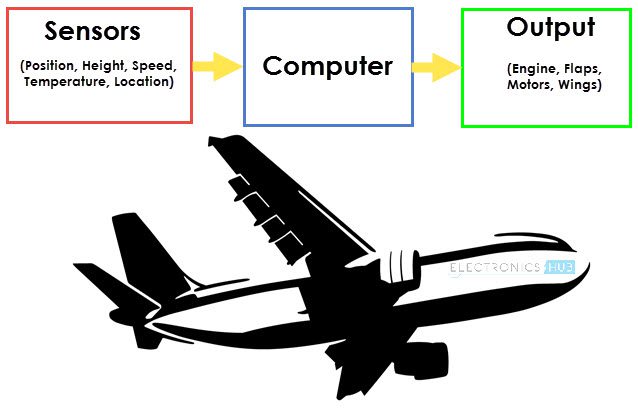
An Automatic Flight Control System consists of several sensors for various tasks like speed control, height, position, doors, obstacle, fuel, maneuvering and many more. A Computer takes data from all these sensors and processes them by comparing them with pre-designed values.
The computer then provides control signal to different parts like engines, flaps, rudders etc. that help in a smooth flight. The combination of Sensors, Computers and Mechanics makes it possible to run the plane in Autopilot Mode.
All the parameters i.e. the Sensors (which give inputs to the Computers), the Computers (the brains of the system) and the mechanics (the outputs of the system like engines and motors) are equally important in building a successful automated system.
But in this tutorial, we will be concentrating on the Sensors part of a system and look at different concepts associated with Sensors (like types, characteristics, classification etc.).
What is a Sensor?
There are numerous definitions as to what a sensor is but I would like to define a Sensor as an input device which provides an output (signal) with respect to a specific physical quantity (input).
The term “input device” in the definition of a Sensor means that it is part of a bigger system which provides input to a main control system (like a Processor or a Microcontroller).
Another unique definition of a Sensor is as follows: It is a device that converts signals from one energy domain to electrical domain. The definition of the Sensor can be understood if we take an example in to consideration.
The simplest example of a sensor is an LDR or a Light Dependent Resistor. It is a device, whose resistance varies according to intensity of light it is subjected to. When the light falling on an LDR is more, its resistance becomes very less and when the light is less, well, the resistance of the LDR becomes very high.
We can connect this LDR in a voltage divider (along with other resistor) and check the voltage drop across the LDR. This voltage can be calibrated to the amount of light falling on the LDR. Hence, a Light Sensor.
Now that we have seen what a sensor is, we will proceed further with the classification of Sensors.
Classification of Sensors
There are several classifications of sensors made by different authors and experts. Some are very simple and some are very complex. The following classification of sensors may already be used by an expert in the subject but this is a very simple classification of sensors.
In the first classification of the sensors, they are divided in to Active and Passive. Active Sensors are those which require an external excitation signal or a power signal.
Passive Sensors, on the other hand, do not require any external power signal and directly generates output response.
The other type of classification is based on the means of detection used in the sensor. Some of the means of detection are Electric, Biological, Chemical, Radioactive etc.
The next classification is based on conversion phenomenon i.e. the input and the output. Some of the common conversion phenomena are Photoelectric, Thermoelectric, Electrochemical, Electromagnetic, Thermo optic, etc.
The final classification of the sensors are Analog and Digital Sensors. Analog Sensors produce an analog output i.e. a continuous output signal with respect to the quantity being measured.
Digital Sensors, in contrast to Analog Sensors, work with discrete or digital data. The data in digital sensors, which is used for conversion and transmission, is digital in nature.
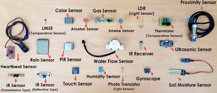
Different Types of Sensors
The following is a list of different types of sensors that are commonly used in various applications. All these sensors are used for measuring one of the physical properties like Temperature, Resistance, Capacitance, Conduction, Heat Transfer etc.
- Temperature Sensor
- Proximity Sensor
- Accelerometer
- IR Sensor (Infrared Sensor)
- Pressure Sensor
- Light Sensor
- Ultrasonic Sensor
- Smoke, Gas and Alcohol Sensor
- Touch Sensor
- Color Sensor
- Humidity Sensor
- Tilt Sensor
- Flow and Level Sensor
We will see about few of the above mentioned sensors in brief. More information about the sensors will be added subsequently. A list of projects using the above sensors is given at the end of the page.
Temperature Sensor
One of the most common and most popular sensor is the Temperature Sensor. A Temperature Sensor, as the name suggests, senses the temperature i.e. it measures the changes in the temperature.
In a Temperature Sensor, the changes in the Temperature correspond to change in its physical property like resistance or voltage.
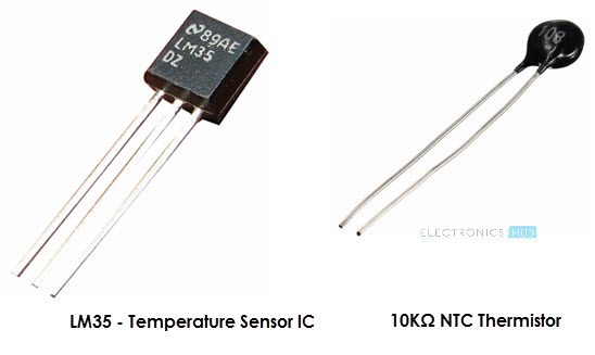
There are different types of Temperature Sensors like Temperature Sensor ICs (like LM35), Thermistors, Thermocouples, RTD (Resistive Temperature Devices), etc.
Temperature Sensors are used everywhere like computers, mobile phones, automobiles, air conditioning systems, industries etc.
A simple project using LM35 (Celsius Scale Temperature Sensor) is implemented in this project: TEMPERATURE CONTROLLED SYSTEM.
Proximity Sensors
A Proximity Sensor is a non-contact type sensor that detects the presence of an object. Proximity Sensors can be implemented using different techniques like Optical (like Infrared or Laser), Ultrasonic, Hall Effect, Capacitive, etc.
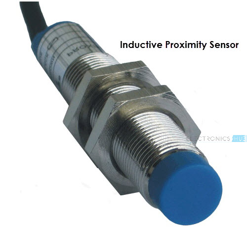
Some of the applications of Proximity Sensors are Mobile Phones, Cars (Parking Sensors), industries (object alignment), Ground Proximity in Aircrafts, etc.
Proximity Sensor in Reverse Parking is implemented in this Project: REVERSE PARKING SENSOR CIRCUIT.
Infrared Sensor (IR Sensor)
IR Sensors or Infrared Sensor are light based sensor that are used in various applications like Proximity and Object Detection. IR Sensors are used as proximity sensors in almost all mobile phones.
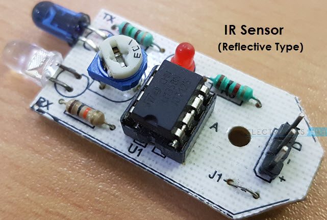
There are two types of Infrared or IR Sensors: Transmissive Type and Reflective Type. In Transmissive Type IR Sensor, the IR Transmitter (usually an IR LED) and the IR Detector (usually a Photo Diode) are positioned facing each other so that when an object passes between them, the sensor detects the object.
The other type of IR Sensor is a Reflective Type IR Sensor. In this, the transmitter and the detector are positioned adjacent to each other facing the object. When an object comes in front of the sensor, the sensor detects the object.
Different applications where IR Sensor is implemented are Mobile Phones, Robots, Industrial assembly, automobiles etc.
A small project, where IR Sensors are used to turn on street lights: STREET LIGHTS USING IR SENSORS.
Ultrasonic Sensor
An Ultrasonic Sensor is a non-contact type device that can be used to measure distance as well as velocity of an object. An Ultrasonic Sensor works based on the properties of the sound waves with frequency greater than that of the human audible range.
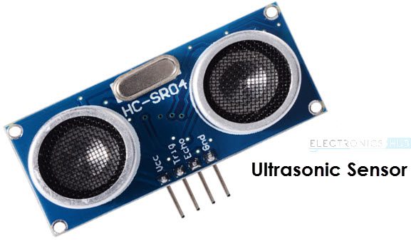
Using the time of flight of the sound wave, an Ultrasonic Sensor can measure the distance of the object (similar to SONAR). The Doppler Shift property of the sound wave is used to measure the velocity of an object.
Arduino based Range Finder is a simple project using Ultrasonic Sensor: PORTABLE ULTRASONIC RANGE METER.
The following is a small list of projects based on few of the above mentioned Sensors.
Light Sensor – LIGHT DETECTOR USING LDR
Smoke Sensor – SMOKE DETECTOR ALARM CIRCUIT
Alcohol Sensor – HOW TO MAKE ALCOHOL BREATHALYZER CIRCUIT?
Touch Sensor – TOUCH DIMMER SWITCH CIRCUIT USING ARDUINO
Color Sensor – ARDUINO BASED COLOR DETECTOR
Humidity Sensor – DHT11 HUMIDITY SENSOR ON ARDUINO
Tilt Sensor – HOW TO MAKE A TILT SENSOR WITH ARDUINO?
In this article, we have seen about What is a Sensor, what are the classification of sensors and different Types of Sensors along with their practical applications.